
알기 쉬운 기술 지식, 한 눈에 보는 업체 비교
01. Geometric Tolerance - (1) Flatness and Parallelism & Conceptual distinction. 본문
01. Geometric Tolerance - (1) Flatness and Parallelism & Conceptual distinction.
Do what you love 2021. 10. 2. 01:57In this posting, we will look at Geometric Tolerance(Geometric Dimensioning and Tolerancing, GD&T),
especially Flatness and Parallelism (definition, reason for use),
and distinguish between the two concepts.
(Note that the Geometric Tolerance is basically a symbol used in the drawing of the part.)
1. What is a Flatness?
A. Definition.
- Tolerance indicated in the drawing how flat the plane of the part should be made.
- That is, the tolerance indicated in the drawing to what extent (mm or micrometer) of unevenness is used on the plane.
B. Reasons for use and examples and methods of marking.

- It is used to make certain surfaces of the parts flat to the desired level.
- For example, let's say we manufacture parts as shown in Figure A.
For production, drawings must be prepared as shown in Figure B below.

In this case, in order for the bottom surface of the component
to be manufactured flat, Flatness GD&T must be applied
to the bottom surface as shown in Figure B.

- If no Flatness GD&T is applied, uneveness may occur as shown in Figure C, resulting in unwanted defective products.
- If the Flatness with Figure B is given, there is a restriction that it should be manufactured within 0.02mm
even if irregularities occur as shown in the figure on the right of Figure D.

Accordingly, a flat component surface desired by the designer
may be obtained by assigning an underlying gap.
- The notation of Flatness is shown in the figure on the left of Figure D.
2. What is parallelism?
A. Definition.
- Tolerance indicated in the drawing how parallel the plane of the component should be to the reference plane.
B. Reasons for use and examples and methods of marking.
- It is used to ensure that a specific surface of the component is manufactured parallel to a certain reference surface at a desired level.
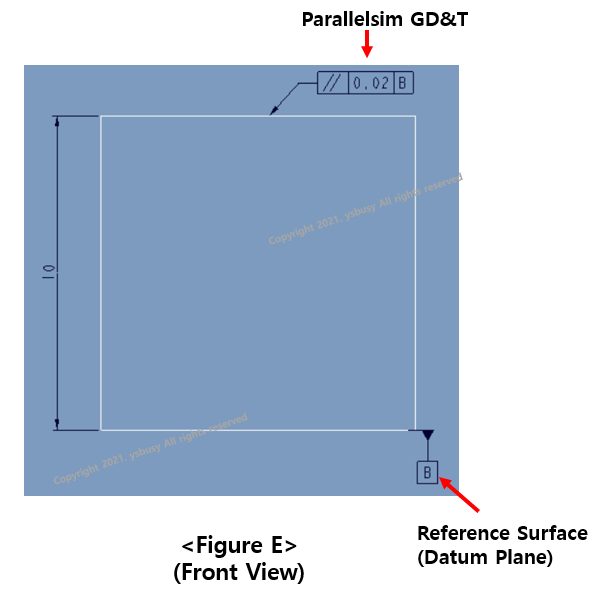
- For example, let's say we manufacture parts as shown in Figure A at the top of the article. For production, drawings must be prepared as shown in Figure E.

In this case, in order for the upper surface of the component to be manufactured parallel to the bottom surface, the bottom surface must be set as a plane B as shown in Figure E above, and a parallelism must be applied to the top surface.
- If the bottom and top surfaces of the component are not parallel, assembly problems may occur, and if they do not need to be parallel, there is no need to apply an underground gap.
- The notation of parallelism is shown in Figure F.
3. Comparision of Flatness and Parallelism.
- The similarity and differences between Flatness and parallelism.

The above article is for reference to help the company's purchasing, sales, and design personnel.
Unauthorized distribution is prohibited.

